0-10 Volt Dimming Wiring Diagram With Daylight Savings Lutron
A lot of people are used to the old rotary dimmers which are completel. And radio powr savr sensors.
0 10v Led Dimming Wiring Diagram Wiring Diagram

Electrical tape or a wire connector to cover.

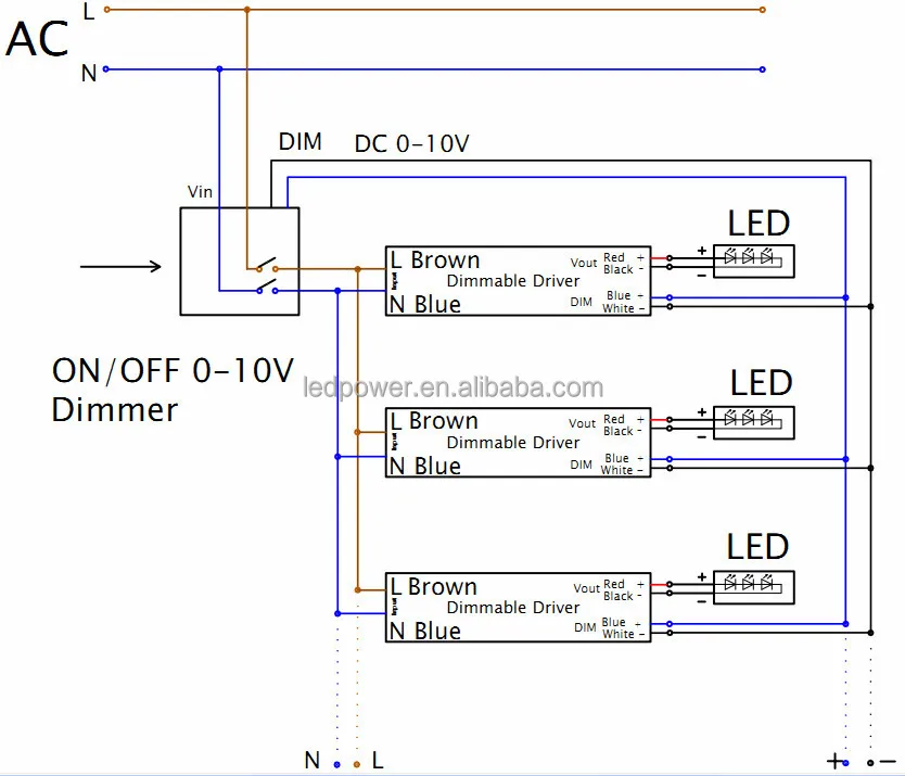
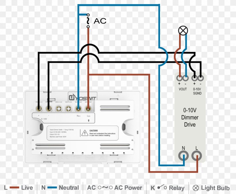
0-10 volt dimming wiring diagram with daylight savings lutron. Line.maestro 0 10v dimming wiring diagram (nov 29, ) ―. Simply put, the control signal is a dc voltage that varies between zero and ten volts. It really is intended to help all the typical person in creating a correct system.
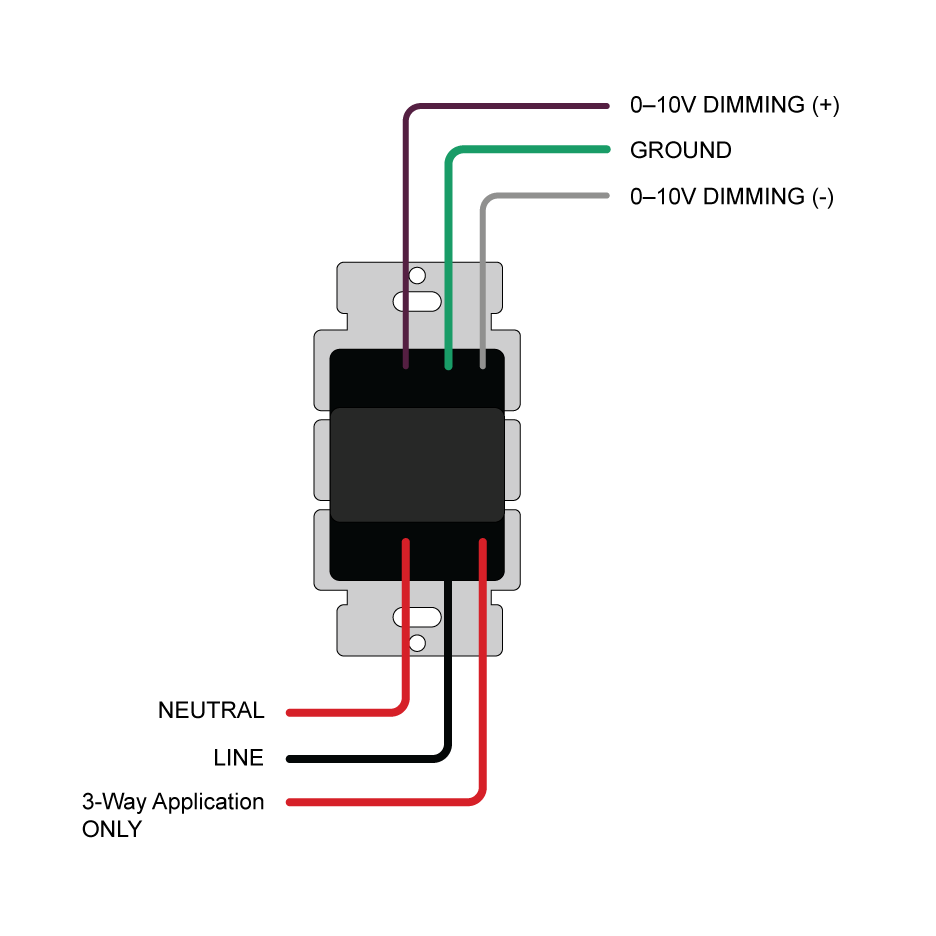
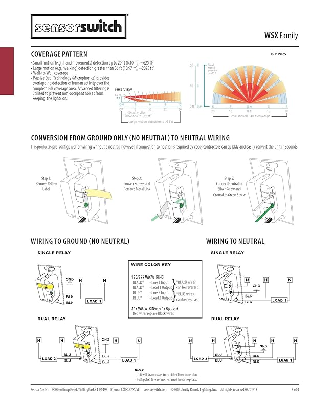
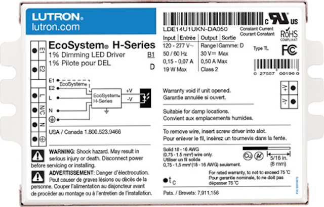
0 volts is full dim, 10 volts is full bright. • violet dimmer lead to (+) violet connection on ballast. The controlled lighting should scale its output so that at 10 v, the controlled light should be at 100% of its potential output, and at 0 v it should at the lowest possible dimming level.
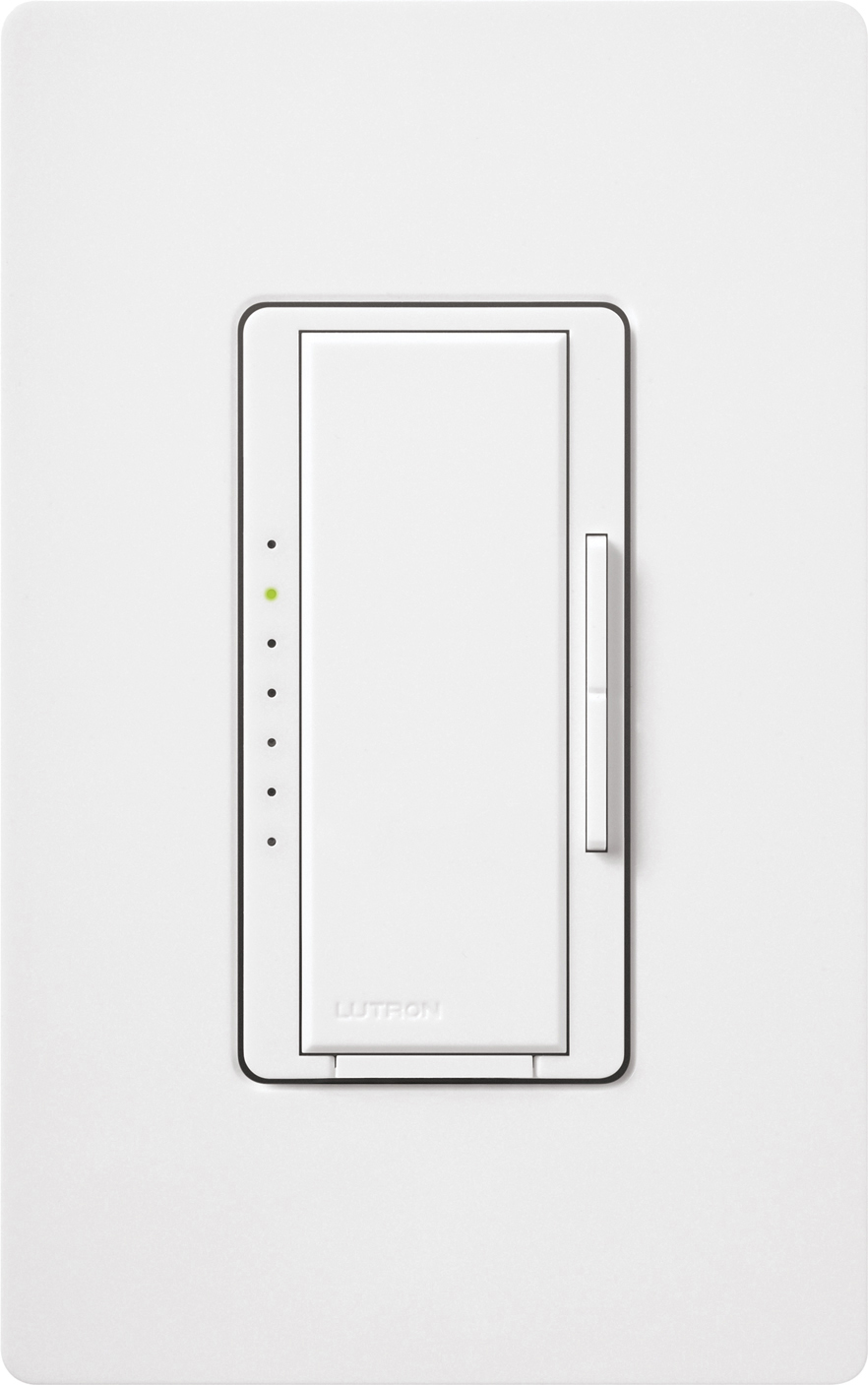
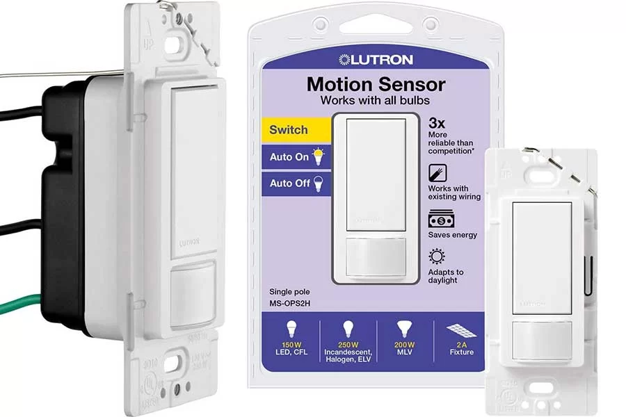
The lutron ecosystem® dimming wiring diagram. Coordinating wall plate sold separately. Add up to three occupancy/ vacancy sensors per dimmer or switch for maximum coverage.
There are many things to consider for your specific application (inrush current, polarity of low voltage wiring, class 1 vs. If you take a dc voltmeter, you will see the driver will create its own 10 vdc signal when the wires are open. Lutron | 3 daylight sensor benefits saves energy • reduces energy consumption by dimming or turning off electric lights based on the natural daylight entering the space • 2can deliver up to 60% lighting energy savings in some areas provides comfort and convenience • helps maintain the proper light level for a space, so a space is never too dark or too bright
At 10volt (10v) the luminare will go to 100 percent or full light output and at 0 volts (0v) it should at 0 percent or output which is off. If you disconnect the purple and grey from the fixtures, (at the dimmer) short them together, (the run going to the fixtures) the lights will dim as low as the driver will allow. This is a simple explanation on connecting 0 to 10 volt dimmers to led light fixtures.
Read further on about how most fixtures do not actually dim to off. As the led industry expands, this technology is becoming a little more complicated. Wiring diagram arrives with several easy to follow wiring diagram guidelines.
Radio powr savr sensors are part of a system and cannot be used to control a load without a compatible rf dimming or switching device. Easily turn the lights on and off with the large paddle switch and use the slide control to adjust the lights to. Wiring diagram also gives beneficial suggestions for tasks that might demand some additional equipment.
• radio powr savr wireless occupancy/vacancy sensors • radio powr savr daylight sensors • pico wireless remotes • maestro wireless dimmers, switches, and sensors • powpak dimming and switching modules • powpak receptacle control modules Ttlp spec and typical wiring diagram. These instructions will likely be easy to comprehend and use.
• most fixtures are sourcing and require a sinking control, per standards as specified by iec 60629. Depending on the information we had from adwords, maestro 0 10v dimming wiring diagram has very much. This simple lighting control system connects to your led fixtures to provide multipurpose lighting solutions and ambiance.
It is the default dimming driver provided with our warm glow dimming, color select and max output product lines, among others. Communication with rf input devices (e.g., pico wireless controls, radio powr savr sensors) is accomplished by using lutron clear connect rf technology.
010V Low Voltage Wall Mount Dimming Control

0 10v Led Dimming Wiring Diagram General Wiring Diagram
26 0 10v Led Dimming Wiring Diagram Wiring Database 2020
Wiring Manual PDF 10v Led Wiring Diagram
LUTRON Maestro 010V Dimmer Sensor Low Voltage Sinking Control

0 10v Dimming Led Downlight Wiring Diagram Wiring Diagram Schemas
Wiring Diagram For Led Dimmer Wiring Diagram Schemas
[DS02] Daylight Sensor Hytronik

Wiring Manual PDF 0 10v Dimming Led Downlight Wiring Diagram
Hubbell Occupancy Sensor Wiring Diagram
LUTRON Maestro 010V Dimmer Sensor Low Voltage Sinking Control

0 10v Led Dimming Wiring Diagram General Wiring Diagram
Understand the hidden costs of free 010V LED dimming drivers (MAGAZINE) LEDs Magazine
Best Programmable Light Switch Home Automation
Wiring Manual PDF 10v Led Wiring Diagram

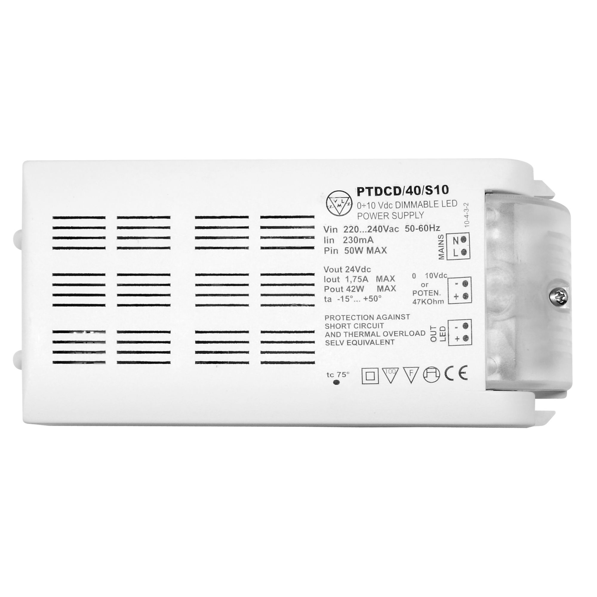
110V Dimmable LED Driver (Constant Voltage) White 42W 24V Mr Resistor Lighting
010 V Lighting Control Dimmer Wiring Diagram Lighting Control System, PNG, 1140x937px, 010 V
Wiring Diagram For Led Dimmer Wiring Diagram Schemas
