24 Volt Alternator Wiring Diagram
If not, the structure will not function as it ought to be. The john deere 24 volt electrical system the proper wiring diagram for the alternatorregulator showing all connections for this application.
1224 Volt DC 10 amp Charging Transformer
It’s supposed to assist all the typical user in developing a suitable method.

24 volt alternator wiring diagram. It’s intended to assist all of the average consumer in creating a proper system. 12 volt system controlling one side of the tractor 3. For obtaining additional wiring installation information, see heavy duty application manuals or contact a remy inc.
Wiring diagram arrives with several easy to stick to wiring diagram directions. 1 trick that we 2 to printing a similar wiring plan off twice. The basic operating principles are explained as follows.
#24 volt delco 10si three wire alternator diagram. Db electrical adr0154 new alternator (40 amp 24 volt) compatible with/replacement for 10si delco 1 wire hookup, 1102916, ty6752, 1102916 ty6752 7129. When you make use of your finger or perhaps the actual circuit with your eyes, it is easy to mistrace the circuit.
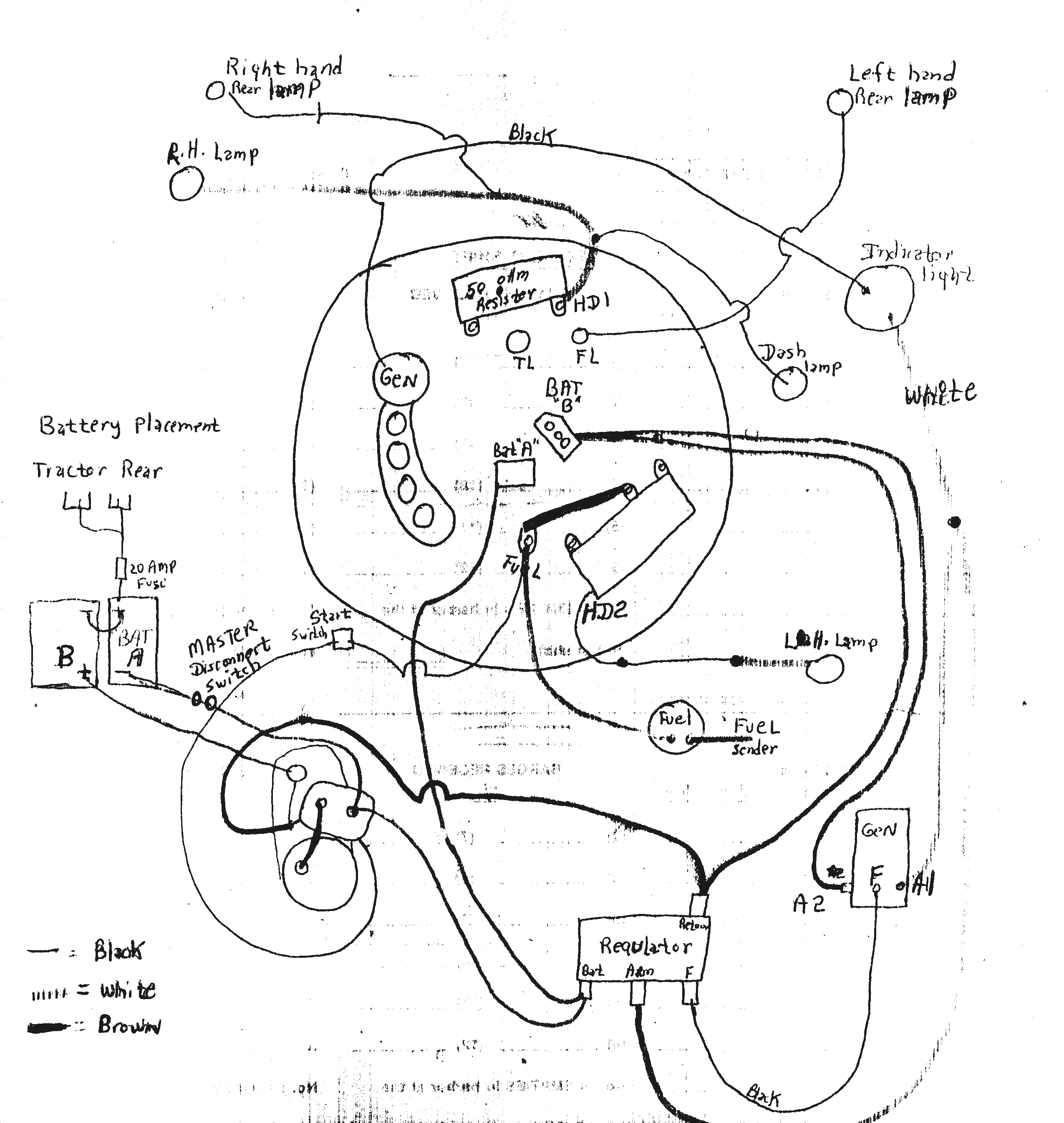
12 volt system controlling the opposite side of the tractor 24 volt alternator installation 12v externally regulated leece neville 24v 175a j advanced regulator 3 wire diagram 9l1841 assembly 12 62 contents quick reference in an output test under load question on gm wiring system serial voltage regulation 101 with jd 4020 paginated for pdf qxd the old again d8k delco remy dra3553 to. The electrical system used on john deere diesel tractors with electric start is a 24 volt split load system.
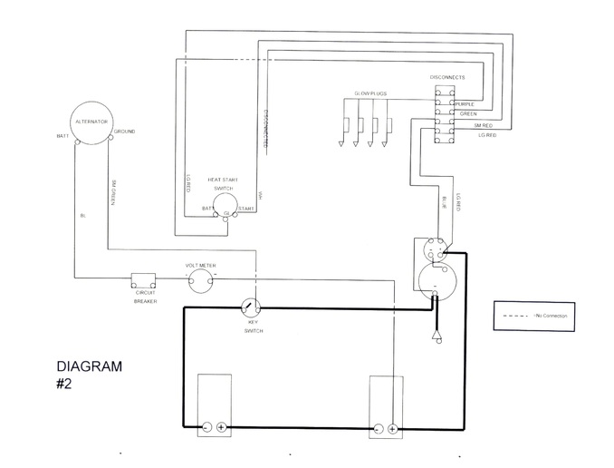
John deere 4020 24v wiring diagram. Wiring diagram for 24 volt starter: Connect alternator to balmar regulator wiring harness as indicated in wiring diagram included on page 12.
These instructions will likely be easy to understand and implement. 4.3 out of 5 stars. 4 wire alternator wiring diagram.
Prestolite 8rg3008 24 volt alternator wiring diagram pdf. One wire goes to the starter motor. This voltage down the exciter wire to the alternator.
The starter generator and regulator all have positive and negative connections and are isolated from the frame, thus they all have a floating ground. The 24 volt electrical system. 13+ 24 volt alternator wiring diagram.
Place the sensor on the end of the multimeter red wire onto the starter motor terminal. Print the wiring diagram off plus use highlighters to trace the signal. Mon jan 25, 2010 5:27 am post subject:
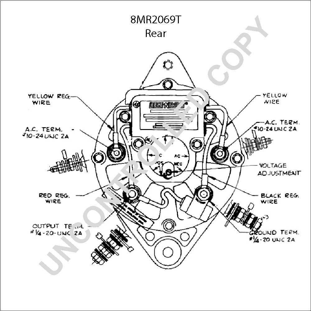
Oct 24, · gahi's diagram is the correct way to wire a gm 10si/12si, and utilize all the benefits of that great. To identify an alternator system, inspect wire or wires that come from under or behind the blower housing. Sat jul 14, 2018 9:38 am post subject:
1 trick that we 2 to printing a. Jd 24v alternator wiring in reply to quake, the 24v jd system is not a true 24v system. (24v system) (alternator output [b+] terminal to battery positive terminal at full output).
Then the charge volts across the battery bank should read 26 to 29. Haveing trouble with the 24 volt box on back of the alternator catching on fire where the stator wire goes into the box. The alternator’s positive and ground cables should be sized according to the chart on page 3.
Place the metal sensor on the end of the black wire onto a clean metal surface. Jd 4020 24v alternator wiring. Tom43 on a 4020 24 volt system, the starter generator and regulator are not positive ground to the frame.
24 volt alternator installation 3 wire regulator diagram advanced self build adjule controler 12v externally regulated voltage regulation 101 with wiring my ih8mud forum battery combiner for victron lithium in an output test under load 15a dc charger by energy minn kota 100 amp to. A typical 10si series wiring diagram is illustrated in figure 3. Follow engine or vehicle manufacturer’s instructions for removing the old alternator from the
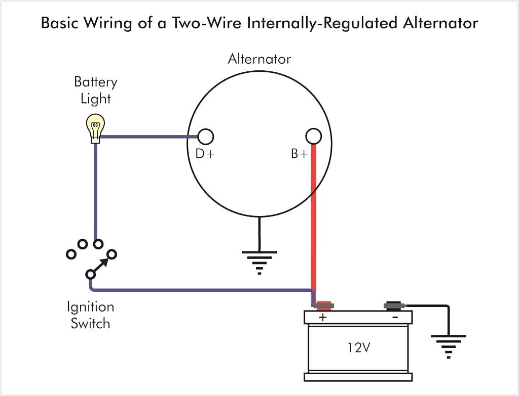
When you make use of your finger or perhaps the actual circuit with your eyes, it is easy to mistrace the circuit. 21 exciter wire battery light key switch to battery as mentioned before we need the correct voltage at the alternator for it to operate properly. Alternator voltage regulation 101 with wiring diagrams in the garage carparts com.
If a new regulator is being installed along with the alternator, complete its wiring. Unless you have an isolated ground alternator, the alternator is already grounded to the chassis thorough it's frame, and keeping the 24 volt system isolated from the chassis. Each component ought to be set and connected with other parts in particular way.
24 volt starting system 2. 2 alternator basic wiring diagram. 24 volt starter solenoid wiring diagram from www.gonefcon.com.
Would anybody happen to have a wireing diagram that would show where the battery cables, and the wires from the alternator go, or have any ideas what would cause this. Wiring diagram comes with numerous easy to stick to wiring diagram instructions. These guidelines will likely be easy to grasp and apply.
(tach) wire if needed and other necessary wiring. The casing of the starter motor is fine. Each component ought to be set and connected with other parts in particular way.
I am going to start off this instructable ground and negative ground with an isolated 24v starting/charging system. Basically there are 3 separate electrical systems within the one main system. John deere 24v to 12v conversion:
I've seen a lot of videos where people mount charging systems in their boats and plug them in to charge when they get home. Assortment of 12 volt alternator wiring schematic. Does anyone have a wiring diagram for this.
A wiring diagram is a streamlined standard pictorial representation of an electrical circuit. Follow the red wire from the alternator towards the battery and you'll see that it splits into two wires. Print the wiring diagram off plus use highlighters to trace the signal.
My diagram shows the starter and the negative side of the battery grounded to the frame/chassis. Should the voltage raise or decrease drastically, the regulator will increase or decrease the output of the alternator to maintain a steady flow of voltage to the battery.
Porsche 24 Volt Alternator Wiring Wiring Diagram
The John Deere 24 Volt Electrical System Explained
24 Volt Battery Wiring Diagram — UNTPIKAPPS

8238 John Deere 24 Volt Alternator Wiring Diagram Epub

Porsche 24 Volt Alternator Wiring Wiring Diagram

2H Alternator Questions Identifying a 24v vs 12v
Skytronic Jasco Alternator 24 Volt Wiring Diagram
Need wiring diagram to convert 24v starter/generator to

24 Volt Battery Wiring Diagram — UNTPIKAPPS

41DD 24 Volt 8030 Alternator Wiring Diagram Ebook Databases

Wiring Diagram 24 Volt Alternator Irish Connections
24 Volt Alternator Wiring Diagram Collection Wiring
24 Volt Alternator Wiring Diagram Database

24V Alternator Wiring Diagram Wiring Diagram And

24 Volt Alternator Wiring Diagram Collection Wiring

Skytronics Jasco Alternator 24 Volt Wiring Diagram
Wiring Diagram For 24 Volt Trolling Motor

24 Volt Alternator Wiring Diagram Collection Wiring
4020 12 Volt Alternator Wiring Diagram Wiring Forums
